How far can Zephyr RTOS go with 16 KB of RAM?
In this article we explore running Zephyr RTOS on the PIC32CM MC00 Curiosity Nano devkit from Microchip. This is not meant to be an introduction to Zephyr RTOS, for that, you can watch the webinars Zephyr RTOS: First Steps and Zephyr RTOS: Building a Complete IoT Application to understand how the build, debug and flashing environment is set up.
Introduction
At the June 2026 Embarcados event, the Embedded Systems & IoT Seminar, I received a board with the PIC32CM1216 microcontroller straight from Rogério Moreira, of Microchip. It is an ARM Cortex-M0 with just 128 KB of Flash and 16 KB of RAM.
Early in my career I had already worked on maintaining code for a product built around a dsPIC33FJ256 (256 KB Flash and 30 KB of RAM). I remember struggling a lot to cut down memory usage. Every byte, function, .c/.h file or misaligned struct counted during the build.
Times have changed, though, and I got curious about how far I could go with only 16 KB of RAM and still build a real application on this devkit, with the added challenge of doing it on Zephyr RTOS as well.
I chose Zephyr RTOS because it already had support for the PIC32CM family and for the sensors, the Modbus protocol and the display I wanted to use in this demo. This devkit has no official Zephyr support, so I had to create an out-of-tree custom board with all the DTS and overlay files for our demo.
The demo
For this article we built a simple monitoring-and-control demo over Modbus. The idea was to bring together, in a single application, the main peripherals and services you typically find in a real embedded product: sensors, a display, I/O expansion, data storage in Flash and industrial communication, all running on Zephyr RTOS.
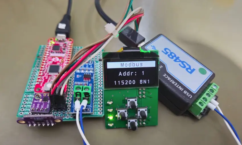
The board acts as a Modbus RTU device (unit id 1, 115200 8N1), exposed through a USB-to-RS485 adapter. Over that bus you can read the sensors, follow the system state and control the outputs (LEDs) remotely. Locally, an OLED display shows operating information and four keys allow direct interaction with the application.
This demo includes the following features:
- Modbus RTU
- VL53L0X distance sensor
- SHT3x temperature and humidity sensor
- SSD1306 OLED display
- Shield with an MCP23008 I²C expander
- 4 LEDs
- 4 keys
- Internal RTC
- Watchdog
- NVS storage using the last 16 KB of internal Flash
- Saves the LED state when the board powers up
- Saves how many times the key has been pressed
- Shell terminal
Electrical connections:
| Pin | Function | Peripheral |
|---|---|---|
| PA00 | UART TX | Console shell |
| PA01 | UART RX | |
| PA08 | I²C SDA | SHT3x, VL53L0X, SSD1306, MCP23008 |
| PA09 | I²C SCL | |
| PA14 | UART TX | Modbus RS-485 |
| PA15 | UART RX | Modbus RS-485 |
| PA10 | GPIO (output) | RS-485 DE/RE |
| PA02 | GPIO (output) | IHM shield RESET |
| PA03 | GPIO (input) | MCP23008 INT |
| PA22 | GPIO (input) | SW0 button |
| PA23 | GPIO (output) | On-board LED0 |
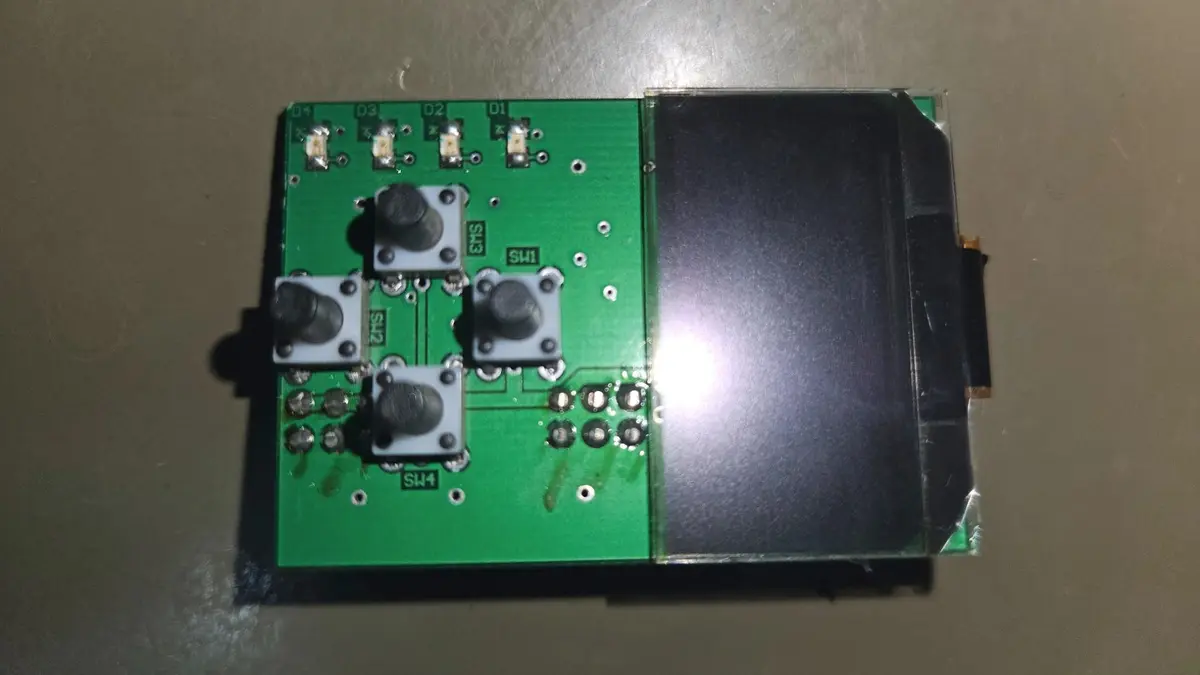 Shield with display, 4 keys and 4 LEDs
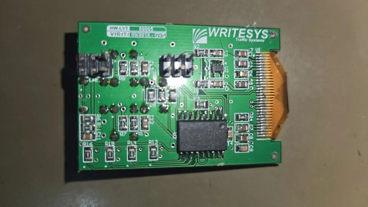 Shield with the MCP23008
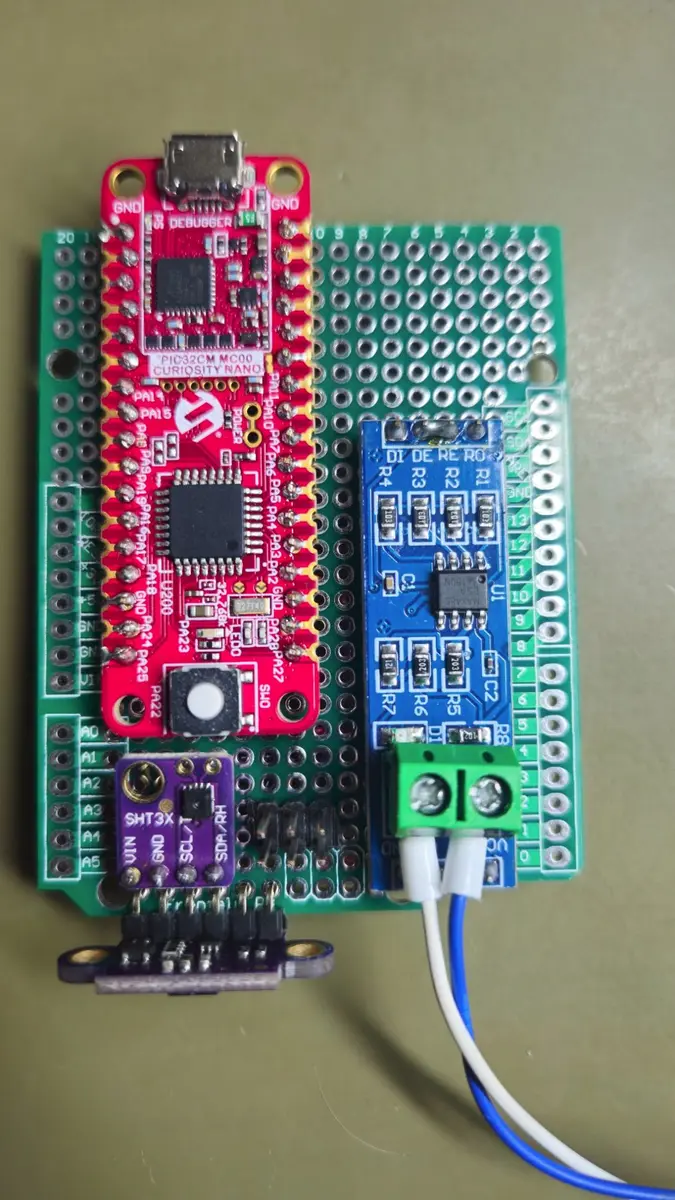 The board assembled for the demo
Flashing and debugging
The devkit already ships with an on-board programmer, which lets us both flash and debug the firmware directly from VSCode using the Cortex-Debug plugin.
To speed up the workflow, we automated the whole process inside VSCode itself:
- We created task runners that wrap the
westcommands (build, flash and the GDB server), removing the need to type commands into the terminal on every cycle. - We set up a debug launch that starts the GDB server (via pyOCD) and connects Cortex-Debug to the board, allowing step-by-step debugging, variable inspection and breakpoints right in the editor. With that, flashing and debugging the application comes down to a single click, making the development cycle much faster and more productive.
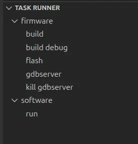 Task runners created
You can find the source code at: https://github.com/JorgeGzm/PIC32-ArtigoZephyr
To run this demo we used:
- Ubuntu 24.04
- Zephyr SDK 1.0.1
- Zephyr Project v4.4.0
Modbus software
To test and validate the Modbus communication, we built a Python application with a graphical interface to monitor and control the device: reading the sensors, showing device information and the number of times the board’s key was pressed, turning the board’s LED on and off, displaying the application uptime, the current RTC value, and running an automatic routine that syncs the RTC date and time with the computer’s clock.
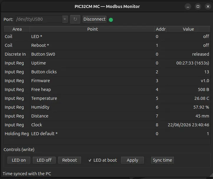 Python software built for the demo
Conclusion
Over the past few years I have moved to working with more powerful microcontrollers. In the last product I worked on, for example, we used an STM32H7 with 2 MB of internal Flash and 1 MB of internal RAM, plus 32 MB of external SDRAM and 16 MB of external NOR Flash.
It was surprising to see everything that was possible with a microcontroller that offers few pins and memory resources considered “limited” (128 KB of Flash and 16 KB of RAM). The demo was able to run a full Zephyr RTOS application while consuming about 105 KB of Flash (80%) and 13.6 KB of RAM (83%).
[223/223] Linking C executable zephyr/zephyr.elf
Memory region         Used Size  Region Size  %age Used
           FLASH:      105276 B       128 KB     80.32%
             RAM:       13624 B        16 KB     83.15%
        IDT_LIST:           0 B        32 KB      0.00%
This demonstration was a reminder of how much times have changed. Code quality, driver abstraction levels and software architecture for embedded systems have all evolved significantly.
As a result, it has become viable to consider more modest microcontrollers, such as the PIC32CM1216, in product development. Combined with Zephyr RTOS, it gains access to a mature ecosystem that supports a wide range of sensors, communication protocols and ready-to-use features, reducing development effort and speeding up the creation of embedded solutions.
This article was first published in Portuguese on the Embarcados portal.
Read the original on Embarcados